DYX-FF-Remote-Cable-Line-Fault-Indicator Main Technical Parameters
- Short circuit sensor mounted cable diameter: outside diameter≤Φ40mm (other specifications shall be customized)
- Earth fault sensor mounted cable diameter: outside diameter≤Φ120mm (other specifications shall be customized)
- Working Ambient Temperature: -40℃-75℃
- Relative Humidity: ≤95%RH
- Working Power Supply: CT power supply when the flowing current above 10A, when the current under 10A, will powered by the backup Lithium battery
- Remote Signal Communication Capacity: AC220V/1A
- Remote Signal Communication Reset Method: Manual reset / Auto reset
- Automatic Reset Time: 1-48H Selectable (accuracy:±1%); Customer could select before production; Default Settings:12H
- Suitable for medium voltage below 35KV rating system.
System Composition
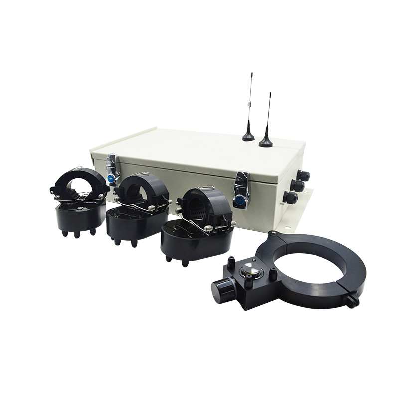
The system of the ground fault indicator is composed of 3 pcs short circuit sensor, 1 pcs earth fault sensor, and 1 pcs data concentration, and the monitoring central station.
Cable Line Installed part include:
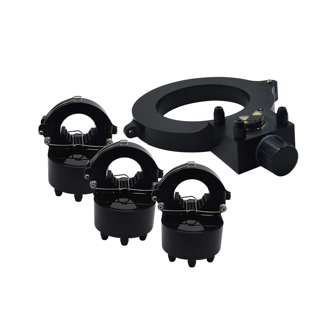
Sensor : 4pcs/SET, include 3 pcs short circuit sensors and 1 pcs earth fault sensor. 3 pcs short circuit sensors respectively installed in A,B,C three phase Cable Line, 1 pcs earth fault sensor installed on the bifurcation unshielded part of three-phase cable.
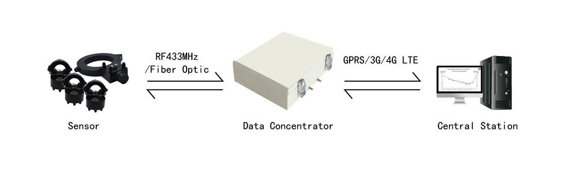
Data Concentrator Unit: Installed inside or outside the Ring Main Unit(or Cable Distribution Box, Switch Cabinet). One data concentrator unit of fault passage indicator can receive fault signal sent by sensors through 433MHz or fiber optic and send to central station through GPRS/3G/4G LTE cellular network. The data concentrator unit of the indicator is mainly composed of industrial modem.
Monitoring central station include:
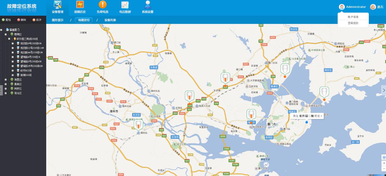
One set data server with software system. Monitoring central station usually setup in power utility office, power substation, etc. When receiving the fault message from the data concentrator unit of the earth fault indicators, combined with GIS system, the maintenance crew man could quickly locate the fault site and trouble-shoot.
The software system could be SCADA or other software platform, usually power utility companies have their own software system. Four-faith also have our own-developed software system.
Note: If customers use their own software system, then should offer Four-faith the software data communication protocol format, so that the FOURFAITH data concentrator could be able to communicate with the software system.
Operation worked example
With the remote monitoring central station, the maintenance crew man could be able to accurately locate the fault section via the GIS in the software system, thus save a lot of time for troubleshooting.
Short circuit indication
On detection of flowing current value exceed the fault sensitivity threshold, the short circuit sensor will send fault signal through 433MHz or fiber optic to the data concentrator, the data concentrator will send the fault signal through GPRS/3G/4G LTE cellular network to the remote central station, the crew man then could quickly identify and locate the fault section and go for troubleshooting at the pointed site.
Earth fault indication
On detection of the zero sequence current value exceed fault sensitivity threshold, the earth fault sensor will send fault signal through 433MHz or fiber optic to the data concentrator, the data concentrator will send the fault signal through GPRS/3G/4G LTE cellular network to the remote central station, the crew man then could quickly identify and locate the fault sectionand go for troubleshooting at the pointed site.
Installation: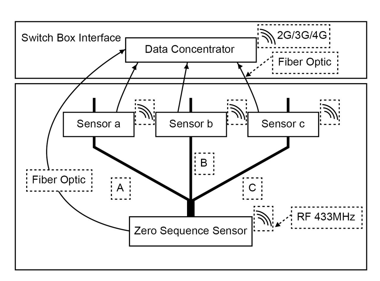
 Chinese
 Overhead Line Fault In
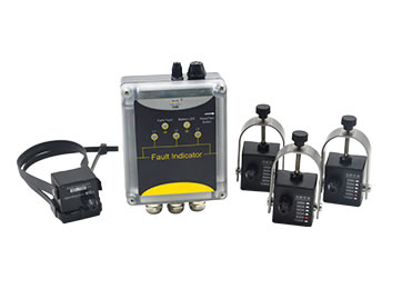 Wall-Mounted Cable Lin
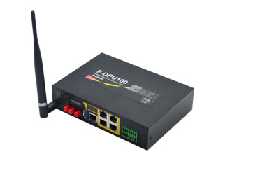 Protocol Converter Gat
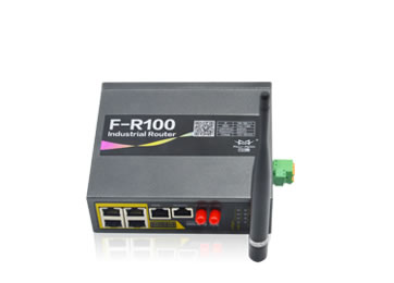 Industrial Cellular Ro
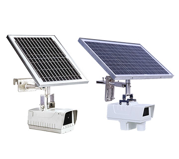 HV Power Line Security
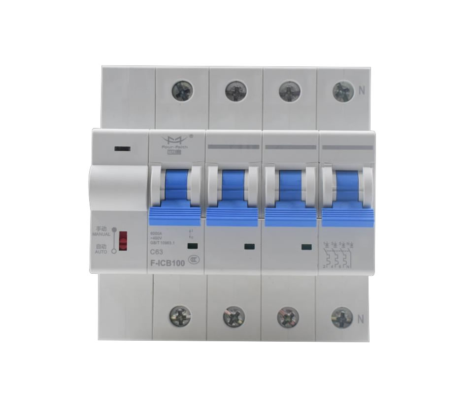 F-ICB100 380V smart ci
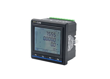 Multifunction Power Me
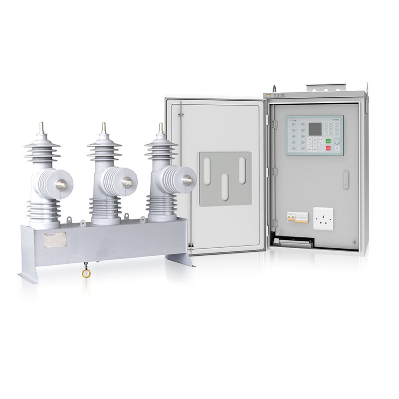 F-FTU200 Auto Circuit
 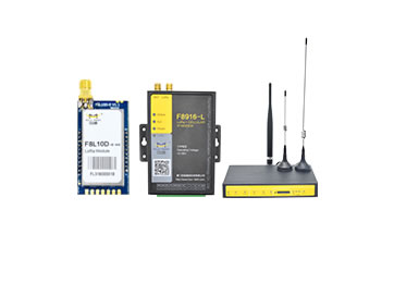 LoRa Module & Gateway
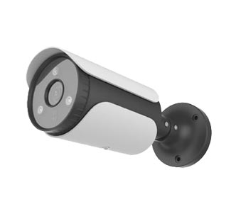 Network Camera
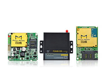 Serial to Cellular
  5G Router
  Download
 Demo
Demo Wiki
Wiki FAQ
FAQ themes