Industrial-Grade Design
- Adopt high performance industrial wireless module
- Adopt high performance industrial 32-bit enhanced processor
- Adopt professional metrology chip
- Built-in real time clock (RTC)
- Adopt ABS flame retardant enclosure
- Wide power input
Powerful Functions
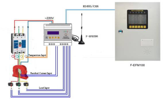
- Provide 3 phase voltage input, 3 phase current input, 3-channel residual current input, 1-channel temperature input, 1-channel CAN bus or RS485
- Support large capacity storage expansion function
- Interactive management: Remote management of platform
Stable & Reliable
- WDT watchdog design, guarantee the system stability
- Input power has over - current protection and over - voltage protection
Standard Interface & Easy to-Use
- Adopts industrial terminal interface, particularly suitable for industrial application
- With CAN bus and RS485 interface, can communicate directly with the corresponding monitor
- Support for LoRa and NB-IoT communications
- Support serial software upgrade and distance maintenance
Standard Compliance
- Electrostatic Discharge Immunity. In accordance with GB/T 17626.2-2006 (IEC 61000-4-2:2001), the severity rating is 3.
- Radiofrequency Electromagnetic Radiation Immunity. In accordance with GB/T 17626.3-2016 (IEC 61000 -4-3:2006), the severity level is 3.
- Electrical Fast Transient Pulse Group Immunity. In accordance with GB/T 17626.4-2008 (IEC 61000-4-4:2004), the severity level is 3.
- Surge Immunity. According to GB/T 17626.5-2008 (IEC 61000-4-5:2005), the severity rating is 3.
- Radio Frequency Transduction Immunity. In accordance with GB/T 17626.6-2008 (IEC 61000-4-6:2006), the severity level is 3.
- Power Frequency Magnetic Field Immunity. In accordance with GB/T 17626.8-2006 (IEC 61000-4-8:2001), the severity rating is 4.
- Voltage Sag and Short Supply Interruption and the Voltage Change Immunity. According to GB/T 17626.11-2008 (IEC 61000 - 4-11:2004), category 3 standard.
Product Function
- Real-time Monitoring, Power Monitoring. The F-EFD200 residual electrical fire monitoring detector can simultaneously measure the three-phase voltage of one circuit, the three-phase current of one circuit, the residual current of one circuit and the temperature of four circuits, and display the current value in real time.
- Alarm Protection Function. When the residual current value of the electrical fire monitoring detector of F-EFD200 exceeds the limit, it will send an audible and visual alarm, which can cut off the loop power supply within the specified time to ensure the safety of electricity consumption.
- Pre-alarm Function. When the residual current in the controlled circuit reaches the preset warning value, the warning light signal is issued, which enables the operator to timely deal with the abnormal situation of the main power distribution circuit and avoid unnecessary faults.
- Alerts. When the voltage, current over limit, will issue overvoltage, undervoltage overcurrent alarm.
- Communicating Function. The detection detector has a variety of communication functions, and can communicate with the monitoring equipment host of the company for networking, realizing remote management, maintenance, control and system upgrade.
parameter
Specifications:
| Characteristic |
| F-EFD200-NB-BL |
| Standard and Frequency Band |
B1: 2100MHz
B3: 1800MHz
B5: 850MHz
B8: 900MHz
B20: 800MHz |
| Theoretical Bandwidth |
100bps~100Kbps |
| Transmit Power |
23dBm±2Db (Max) |
| Receive Sensitivity |
-129dBm |
| F-EFD200-L |
| Standard and Frequency Band |
433MHz |
| Communication Bandwidth |
Level 6 Adjustable (0.3, 0.6, 1.0, 1.8, 3.1, 5.5Kbps) |
| Communication Distance |
Indoor/urban communication distance: 1km
Outdoor/stadia communication distance: 3.5km |
| Transmit Power |
20dBm(100mW) |
| Receive Sensitivity |
-140dBm |
| Hardware System |
| CPU |
Industrial-grade 32-bit enhanced processor |
| FLASH |
512 KB |
| EEPROM |
8KB |
| SRAM |
64KB |
| Interface Type |
| Communication |
RS485 (Optional CAN Bus) |
1 RS485 interface with 15KV ESD protection built in. The serial port parameters are as follows:
Stop Bits: 1, 2
Check: no check, even check, odd check
Serial Port Rate: 1200~38400 Bits/s, Default: 9600 Bits/s
Serial Port Rate: 1200~38400bits/s, default: 9600bits/s |
| This device has 1 CAN bus interface, CAN bus communication is stable and reliable, and can communicate with other external devices to achieve various networking needs |
| NB-IoT |
Support full network access frequency band |
| LoRa |
Support 433, 470 frequency band |
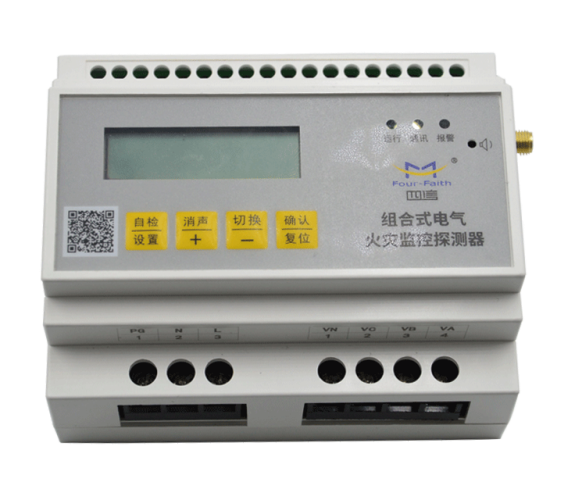
| Human Interface |
LCD |
Using 128*32 LCD screen, display content is rich |
| Indicator Light |
3 status indicators with "running", "communication" and "alarm" |
| Buzzer |
Fault alarm, detect abnormal alarm |
| Button |
4 Buttons, "self-check/set", "muffler /+", "switch, -", "confirm/reset" |
| Application Interface |
Voltage |
1 channel three-phase voltage, overvoltage (≥240V), undervoltage (≤190V), wrong phase |
| Electric Current |
1 channel three-wire current, the current alarm value can be set |
| Residual Current |
1 channel residual current transformer, alarm value setting range: 20 ~ 1000mA |
| Temperature |
4 road temperature probe, measuring range: 0 ℃ ~ 150 ℃, alarm value setting range: 45 ~ 140 ℃ |
| Power Interface |
At the terminal interface, the overcurrent protection ≥120% and overvoltage protection, which can be recovered |
| Note: Different types of accessories and interfaces may be different, subject to the real object. |
| Power Supply |
| Reference Power Supply |
AC 220V 50Hz |
| Power Supply Range |
AC85 - 264V |
| Power Consumption |
| Average Power Consumption |
<0.5W |
| Maximum Dynamic Power Consumption |
|
| Physical Characteristics |
| Housing |
ABS flame retardant material, shell and system safety isolation, especially suitable for power field application |
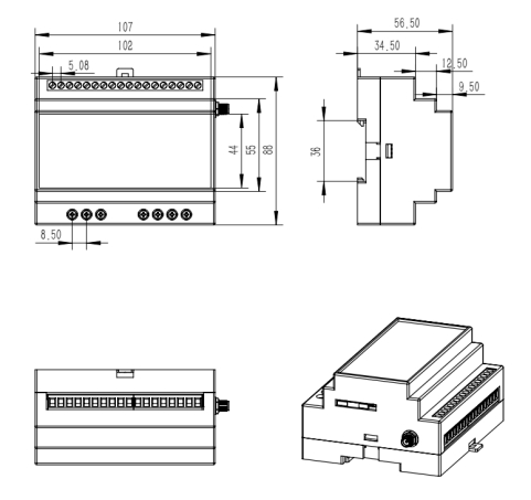
| Dimensions |
107x88x56.5mm (excluding antenna and mounting parts) |
| Weight |
About 550g (including mounting parts and packing) |
| Others Parameters |
| Operating Temperature |
-20~+70ºC |
| Storage Temperature |
-30~+80ºC |
| Relative Humidity |
5%~95% (Non-Condensing) |
| Order Information |
| F-EFD200 |
RS485(optional CAN bus) |
| F-EFD200-L-LR |
LoRa private protocol communications |
| F-EFD200-L-LW |
LoRaWan communication protocol |
| F-EFD200-NB-BL |
NB communication (Full Netcom) |
Appendix A
A.1 Construction
The shape and installation dimensions of the equipment are 35mm track-type installation, which is convenient for users to install quickly. Please refer to the following figure for the specific installation dimensions. (unit: mm)
A.2 Terminals (18PIN spacing 5.08mm,3PIN spacing 8.5mm, 4PIN spacing 8.5mm)
Specification of upper terminal: 18PIN spacing 5.08mm
Down terminal specifications: 3PIN spacing 8.5mm, 4PIN spacing 8.5mm
| NTC1 |
NTC2 |
COM |
NTC2 |
NTC2 |
COM |
GND |
5V |
A+/CANL |
B-/CANH |
IAP |
IAN |
IBP |
IBN |
ICP |
ICN |
INP |
INN |
| 18 |
17 |
16 |
15 |
14 |
13 |
12 |
11 |
10 |
9 |
8 |
7 |
6 |
5 |
4 |
3 |
|
|
Figure 3 Interface Diagram
Terminal Interface Signal Definition:
| No |
Interface Definition |
Description |
| 1 |
INN |
Residual Current Input |
| 2 |
INP |
Residual Current Input |
| 3 |
ICN |
Phase C Current Negative input |
| 4 |
ICP |
Phase C Current Positive input |
| 5 |
IBN |
Phase B Current Negative input |
| 6 |
IBP |
Phase B Current Positive input |
| 7 |
IAN |
Phase A Current Negative input |
| 8 |
IAP |
Phase A Current Positive input |
| 9 |
B-/ CANH |
RS485: B - / CAN bus: H |
| 10 |
A+/ CANL |
RS485: A + / CAN bus: L |
| 11 |
5V |
RS485:5V |
| 12 |
GND |
RS485:GND |
| 13 |
COM |
Temperature sensor input 3,4 common terminals |
| 14 |
NTC4 |
Temperature sensor input 4 |
| 15 |
NTC3 |
Temperature sensor input 3 |
| 16 |
COM |
Temperature sensor input 1,2 common terminals |
| 17 |
NTC2 |
Temperature sensor input 2 |
| 18 |
NTC1 |
Temperature sensor input 1 |
| No |
Interface Definition |
Description |
| 1 |
PG |
Earth |
| 2 |
N |
AC220V Input zero |
| 3 |
L |
AC220V Input wire |
| No |
Interface Definition |
Description |
| 1 |
VN |
Neutral input |
| 2 |
VC |
Phase C Voltage input |
| 3 |
VB |
Phase C Voltage input |
| 4 |
VA |
Phase C Voltage input |
Related Products
-
F-EFD100 Residual Current Monitor
 Chinese
 Communication
 Overhead Line Fault In
 Underground Fault Indi
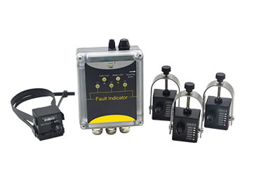 Wall-Mounted Cable Lin
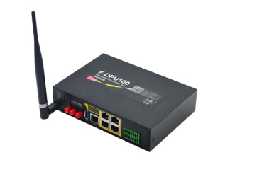 Protocol Converter Gat
 Serial and Ethernet to
 HV Power Line Security
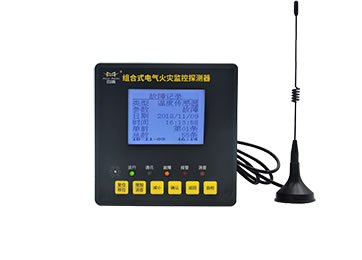 Residual Current Monit
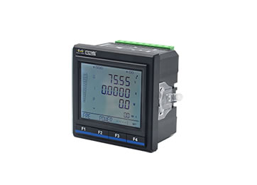 Multifunction Power Me
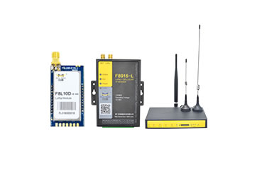 LoRa Module & Gateway
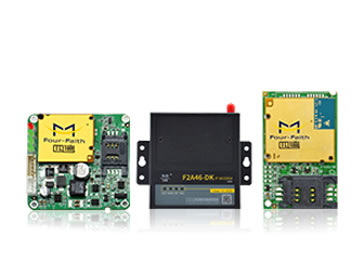 Serial to Cellular
  Download
 Demo
Demo Wiki
Wiki FAQ
FAQ themes